


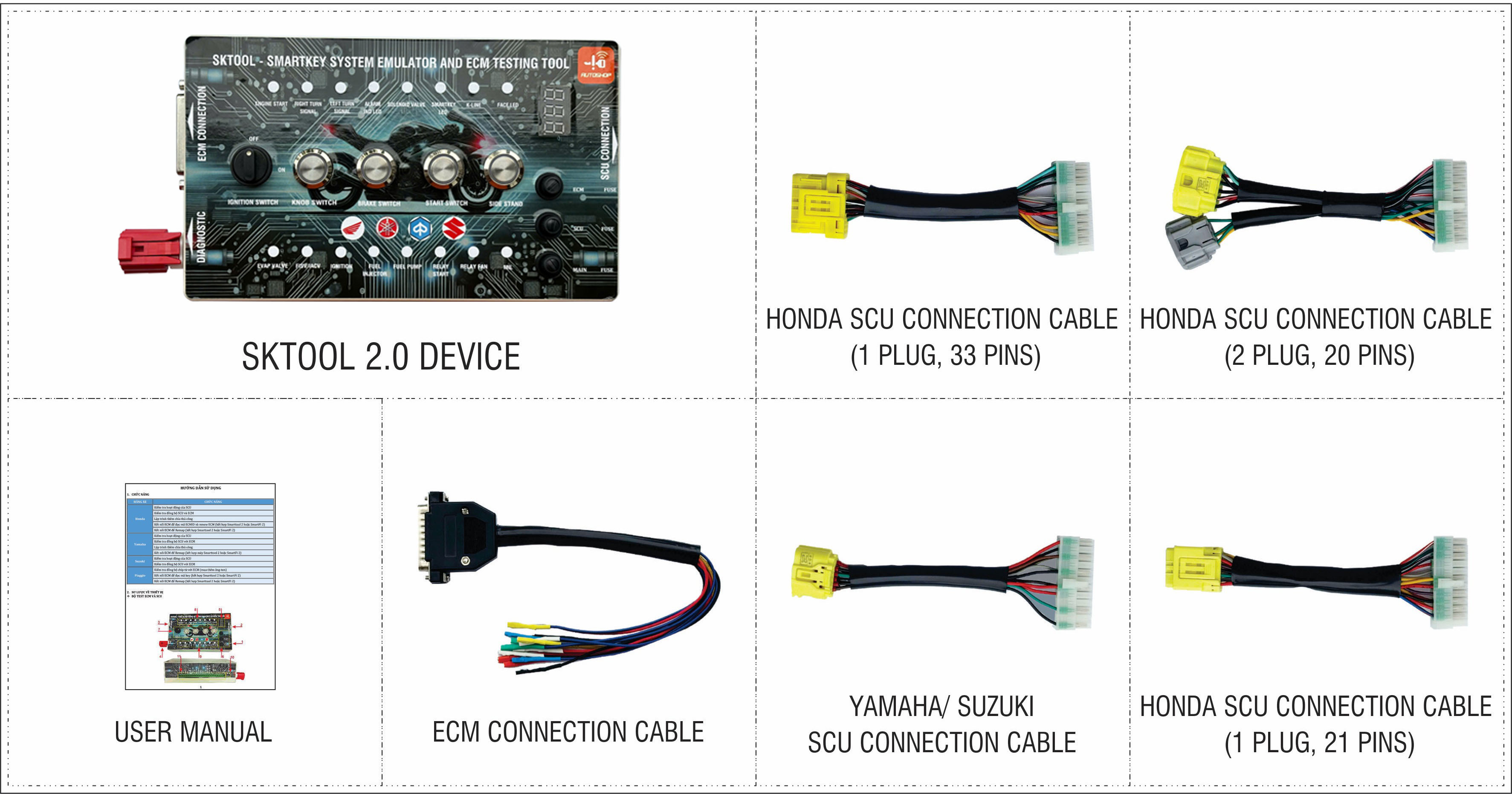
SKTOOL 2.0
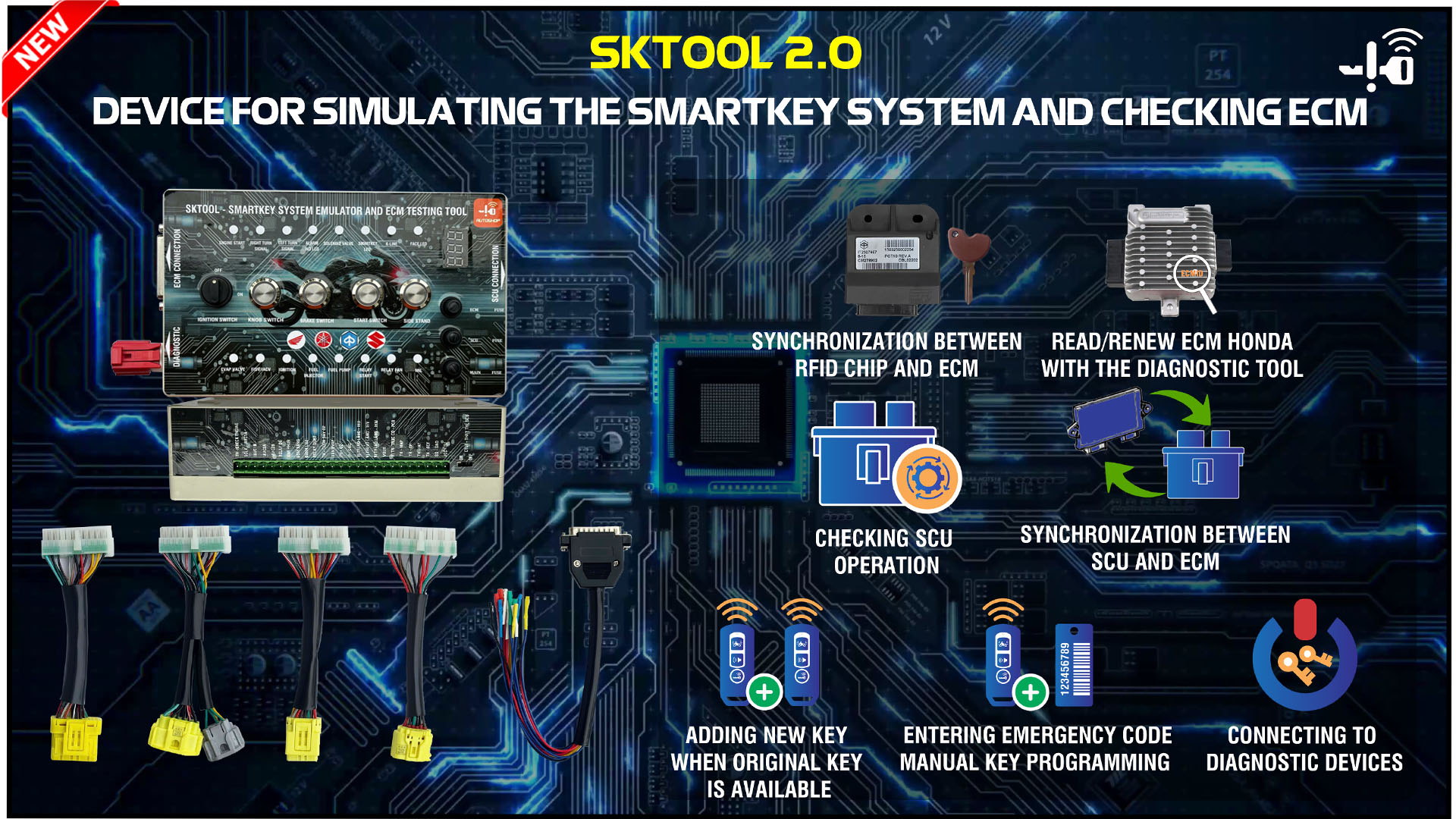
SKTOOL 2.0 is a device that simulates the smart key system and immobilizer system. It supports repairing and testing the SCU module, checking the input and output signals of the ECM, and assisting with diagnostics and remapping on the bench. It is compatible with motorbikes from brands such as HONDA, YAMAHA, PIAGGIO, VESPA, and SUZUKI.


LIST OF FUNCTIONS
1. Check and repair the smart key system for HONDA, YAMAHA, and SUZUKI.
2. Check and repair the immobilizer security system for PIAGGIO/VESPA (additional antenna required).
3. Support for testing the ECM (Engine Control Module) - Upgrade available in the future.
4. Support for connecting ECM/ECU on the bench.
DETAILED FUNCTIONS
1. CHECK AND REPAIR THE SMARTKEY SYSTEM
- Support programming replacement parts such as FOB or SCU on the model.
- Check synchronization between the FOB and SCU or SCU and ECM.
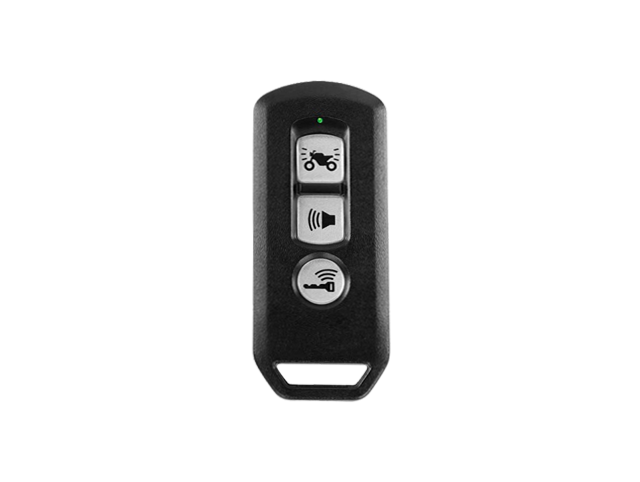
- Test the operation of the FOB and SCU.
- Check the status of input signals in the SCU – ignition switch signal, side stand signal, wake-up switch, and ignition lock.
- Test output control signals in the SCU – solenoid valve, turn signal, smartkey light, and start signal.
- Support measuring and diagnosing faults inside the SCU.
- Provide a list of motorbikes using the smart key system for HONDA, YAMAHA, and SUZUKI.
2. CHECK AND REPAIR THE IMMOBILIZER SECURITY SYSTEM FOR PIAGGIO/VESPA
- Support programming additional manual keys.
- Check synchronization between the immobilizer and ECM/ECU.
- Simulate the immobilizer security system.
(Require the use of an additional antenna from the manufacturer).
3. SUPPORT FOR TESTING ECM (ENGINE CONTROL MODULE)
*This function will be upgraded in the future.
4. SUPPORT FOR CONNECTING ECM/ECU ON THE BENCH - WORKS WITH DIAGNOSTIC EQUIPMENT
- Read/delete error codes on the model.
- Upload software, remap, and unlock RPM limits .
- Turn off the smart key system and immobilizer security system.
- Read/renew IMMOID code in ECM.
- Support brands: HONDA, YAMAHA, SUZUKI, and PIAGGIO.
LIST OF SUPPORTED MOTORBIKES
- HONDA.
- YAMAHA.
- SUZUKI.
- PIAGGIO/VESPA.
SKTOOL 2.0
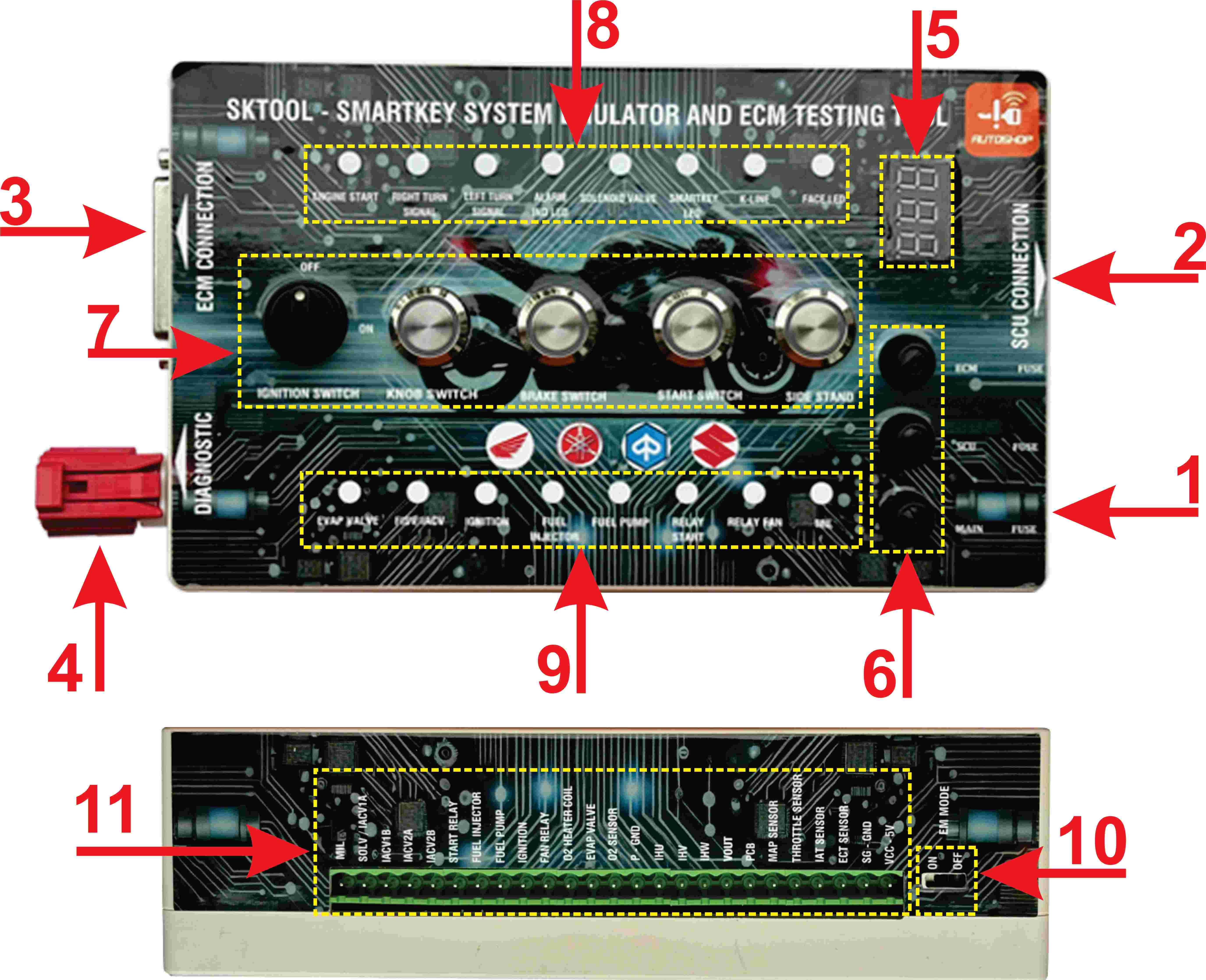
| No. | Component Name | Functions |
| 1 | 12V power connector | Supplies 12V power to the SKTOOL |
| 2 | SCU connection port | Connects the SKTOOL to the SCU |
| 3 | ECM connection port | Connects the SKTOOL to the ECM |
| 4 | Diagnostic connector | Connects the diagnostic devices to the ECM |
| 5 | Voltmeter | Displays the voltage of SKTOOL |
| 6 | Fuse module | Protects the circuit pathways |
| 7 | Switch and button module | Simulates buttons and ignition switches on the motorcycles |
| 8 | SCU Simulated Signal Indicator LED | Displays the SCU’s operating status |
| 9 | ECM Simulated Signal Indicator LED | Displays the ECM’s operating status |
| 10 | Toggle Switch | Switches to manual key programming mode |
| 11 | Standby Connector | Connects for testing the sensors and components |
* CONNECT IMAGE
Image of connection to check the operation of the 20-pin SCU of HONDA motorcycle brand
Image of connection to check the operation of the 21-pin SCU of HONDA motorcycle brand
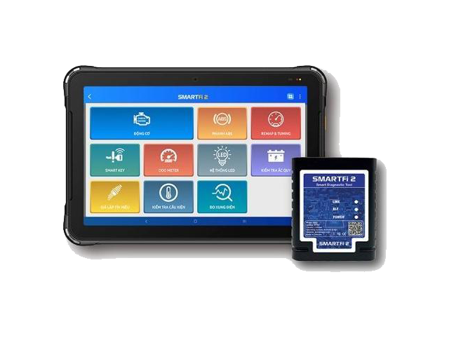
Image of connection to read/delete HONDA ECMID code and Remap ECM on test kit (using SmartFi 2 machine)
Image guide to look up ECM connection pins on ALLMOTO
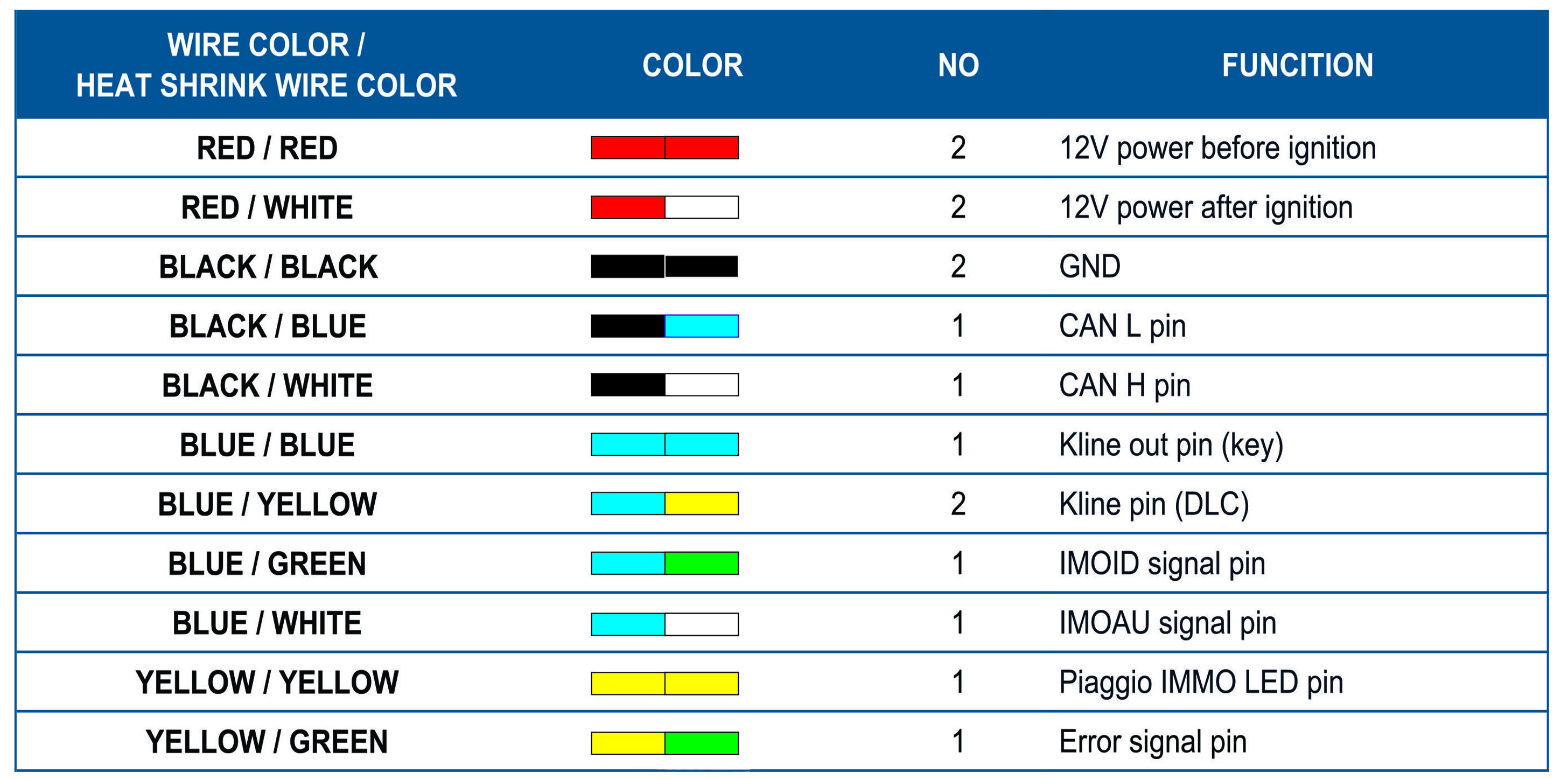
* ECM CONNECTION CABLE COLOR CHART